Заглавная страница Избранные статьи Случайная статья Познавательные статьи Новые добавления Обратная связь FAQ Написать работу КАТЕГОРИИ: ТОП 10 на сайте Приготовление дезинфицирующих растворов различной концентрацииТехника нижней прямой подачи мяча. Франко-прусская война (причины и последствия) Организация работы процедурного кабинета Смысловое и механическое запоминание, их место и роль в усвоении знаний Коммуникативные барьеры и пути их преодоления Обработка изделий медицинского назначения многократного применения Образцы текста публицистического стиля Четыре типа изменения баланса Задачи с ответами для Всероссийской олимпиады по праву 
Мы поможем в написании ваших работ! ЗНАЕТЕ ЛИ ВЫ?
Влияние общества на человека
Приготовление дезинфицирующих растворов различной концентрации Практические работы по географии для 6 класса Организация работы процедурного кабинета Изменения в неживой природе осенью Уборка процедурного кабинета Сольфеджио. Все правила по сольфеджио Балочные системы. Определение реакций опор и моментов защемления |
Torque - Caliper Mounting BoltsСодержание книги
Поиск на нашем сайте
Front: 34 N·m (3.5 kgf·m, 25 ft·lb) Rear: 25 N·m (2.5 kgf·m, 18 ft·lb) Brake Hose Banjo Bolts: 25 N·m (2.5 kgf·m, 18 ft·lb) • Check the fluid level in the brake reservoirs. • Bleed the brake line (see Brake Line Bleeding). • Check the brake for good braking power, no brake drag,
and no fluid leakage.
Front Caliper Disassembly • Refer to the Caliper Rubber Parts Replacement in the Pe- riodic Maintenance chapter. Front Caliper Assembly • Refer to the Caliper Rubber Parts Replacement in the Pe- riodic Maintenance chapter. Rear Caliper Disassembly • Refer to the Caliper Rubber Parts Replacement in the Pe- riodic Maintenance chapter. Rear Caliper Assembly • Refer to the Caliper Rubber Parts Replacement in the Pe- riodic Maintenance chapter.
The fluid seal (piston seal) [A] is placed around the pis- ton to maintain clearance between the pad and the disc. If the seal is in a poor condition, it could lead the pad to wear excessively or the brake to drag, which may cause the tem- perature of the discs or the brake fluid to increase. • Replace the fluid seal if it exhibits any of the conditions listed below. ○Brake fluid leakage around the pad. ○Brakes overheat.
○Seal and piston are stuck together.
well. Also, replace all seals every other time the pads are changed.
• Check that the dust boot [A] and friction boot [B] are not cracked, worn, swollen, or otherwise damaged.
scores or rusty.
The caliper body must slide smoothly on the caliper holder shafts [A]. If the body does not slide smoothly, one pad will wear more than the other, pad wear will increase, and con- stant drag on the disc will raise brake and brake fluid tem- perature. • Check to see that the caliper holder shafts are not badly worn or stepped, and that the rubber friction boots are not damaged.
Front Brake Pad Removal
• Draw out the holder shaft pin [A], and take off the holder shaft [B]. • Remove the pad [C] on the piston side. • Push the holder [D] towards the piston, and remove the pad of the other side [E] from the holder shaft [F].
Front Brake Pad Installation • Push the caliper pistons in by hand as far as they will go. • Install the anti-rattle spring in its correct position. • Install the pad on the piston side first, then install the other pad on the holder.
• Remove the rear caliper with the hose installed (see Rear Caliper Removal). • Draw out the holder shaft pin [A], and take off the holder shaft [B]. • Remove the pad [C] on the piston side. • Push the holder [D] towards the piston, and remove the pad of the other side [E] from the holder shaft [F].
Rear Brake Pad Installation • Push the caliper piston in by hand as far as it will go. • Install the anti-rattle spring in its correct position. • Install the pad on the piston side first, then install the other pad on the holder.
Brake Pad Wear Inspection • Refer to the Brake Pad Wear Inspection in the Periodic Maintenance chapter.
Front Master Cylinder Removal
stallation).
• Unscrew the clamp bolts [B], and take off the master cylin- der as an assembly with the reservoir, brake lever and
brake switch installed.
Brake Lever Pivot Bolt [A] and Locknut Brake Lever [B] Front Brake Light Switch [C]
• Install the front master cylinder so that the punch mark [A] of the handlebar is aligned with the mating surface [B] of the master cylinder clamp to level the reservoir.
• Tighten the upper clamp bolt [B] first, and then the lower clamp bolt [C]. There will be a gap at the lower part of the clamp after tightening. Torque - Front Master Cylinder Clamp Bolts: 8.8 N·m (0.90 kgf·m, 78 in·lb) • Replace the washers on each side of the hose fitting with new ones. • Tighten the brake hose banjo bolt. Torque - Brake Hose Banjo Bolt: 25 N·m (2.5 kgf·m, 18 ft·lb) • Bleed the brake line (see Brake Line Bleeding). • Check the brake for good braking power, no brake drag, and no fluid leakage.
Rear Master Cylinder Removal
• Remove the cotter pin [B]. NOTE ○Pulloff the joint pin while pressing down the brake pedal. • Pull off the reservoir hose lower end [C], and drain the brake fluid into a container. • Remove the master cylinder.
• Replace the cotter pin [A] with a new one. • Replace the washers on each side of hose fitting with new ones. • Tighten the following bolts. Torque - Rear Master Cylinder Mounting Bolts: 25 N·m (2.5 kgf·m, 18 ft·lb) Brake Hose Banjo Bolt: 25 N·m (2.5 kgf·m, 18 ft·lb) • Bleed the brake line (see Brake Line Bleeding). • Check the brake for good braking power, no brake drag, and no fluid leakage. Front Master Cylinder Disassembly • Refer to the Master Cylinder Rubber Parts Replacement in the Periodic Maintenance chapter. Rear Master Cylinder Disassembly • Refer to the Master Cylinder Rubber Parts Replacement in the Periodic Maintenance chapter. Master Cylinder Assembly • Refer to the Master Cylinder Rubber Parts Replacement in the Periodic Maintenance chapter.
• Remove the master cylinders (see Front/Rear Master Cylinder Removal). • Disassemble the front and rear master cylinders. • Check that there are no scratches, rust or pitting on the inner wall [A] of each master cylinder and on the outside of each piston [B].
• Inspect the primary cup [C] and secondary cup [D].
the piston assembly should be replaced to renew the cups.
Front Master Cylinder [J]
• Check the piston return springs [F] for any damage.
• Check that relief port [G] and supply port [H] are not plugged.
Rear Master Cylinder [K]
Brake Disc Removal • Remove the wheel (see Front/Rear Wheel Removal in the Wheels/Tires chapter). • Unscrew the mounting bolts, and take off the disc.
Brake Disc Installation • Replace the gaskets with new ones. • Install the brake disc on the wheel so that the marked side [A] faces out. • Apply a non-permanent locking agent to the threads of the front and rear brake disc mounting bolts [B]. • Tighten: Torque - Brake Disc Mounting Bolts: 27 N·m (2.8 kgf·m, 20 ft·lb)
• Measure the thickness of each disc [A] at the point where it has worn the most.
Brake Discs Thickness Standard: Front: EX650A Models 4.3 ~ 4.7 mm (0.17 ~ 0.19 in.) EX650B Models 4.8 ~ 5.2 mm (0.19 ~ 0.20 in.) Rear 4.8 ~ 5.2 mm (0.19 ~ 0.20 in.) Service Limit: Front 4.0 mm (0.16 in.) Rear 4.5 mm (0.18 in.)
• Raise the wheel off the ground with jack (see Front/Rear Wheel Removal in the Wheels/Tires chapter).
|
||||||||||||
|
|
Последнее изменение этой страницы: 2016-08-10; просмотров: 383; Нарушение авторского права страницы; Мы поможем в написании вашей работы! infopedia.su Все материалы представленные на сайте исключительно с целью ознакомления читателями и не преследуют коммерческих целей или нарушение авторских прав. Обратная связь - 216.73.216.41 (0.006 с.) |


 Caliper Fluid Seal Damage
 ○Considerable difference in inner and outer pad wear.
 If the fluid seal is replaced, replace the dust seal [B] as
 Rear Caliper Dust Boot and Friction Boot Damage
 Caliper Piston and Cylinder Damage
 Rear Caliper Holder Shaft Wear
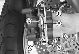 • Remove the front caliper with the hose installed (see Front Caliper Removal).
 Rear Brake Pad Removal
 • Remove the banjo bolt [A] to disconnect the brake hose from the master cylinder [B] (see Brake Hose Removal/In-
 • Disconnect the front brake light switch connectors [A].
 • Remove:
 Front Master Cylinder Installation
 • The master cylinder clamp must be installed with the ar- row mark [A] upward.
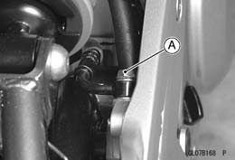 • Unscrew the brake hose banjo bolt [A] on the master cylin- der (see Brake Hose Removal/Installation).
 • Unscrew the master cylinder mounting bolts [A].
 Rear Master Cylinder Installation
 Master Cylinder Inspection
 • Check the dust covers [E] for damage. If they are damaged, replace them.
 • Remove the gaskets.
 Brake Disc Wear
 If the disc has worn past the service limit, replace it. Measuring Area [B]
 Brake Disc Warp