
Заглавная страница Избранные статьи Случайная статья Познавательные статьи Новые добавления Обратная связь FAQ Написать работу КАТЕГОРИИ: ТОП 10 на сайте Приготовление дезинфицирующих растворов различной концентрацииТехника нижней прямой подачи мяча. Франко-прусская война (причины и последствия) Организация работы процедурного кабинета Смысловое и механическое запоминание, их место и роль в усвоении знаний Коммуникативные барьеры и пути их преодоления Обработка изделий медицинского назначения многократного применения Образцы текста публицистического стиля Четыре типа изменения баланса Задачи с ответами для Всероссийской олимпиады по праву 
Мы поможем в написании ваших работ! ЗНАЕТЕ ЛИ ВЫ?
Влияние общества на человека
Приготовление дезинфицирующих растворов различной концентрации Практические работы по географии для 6 класса Организация работы процедурного кабинета Изменения в неживой природе осенью Уборка процедурного кабинета Сольфеджио. Все правила по сольфеджио Балочные системы. Определение реакций опор и моментов защемления |
Pilot Screw Adjuster, E: 57001-1603Содержание книги
Поиск на нашем сайте
Fuel System (DFI) Air Cleaner Element Cleaning NOTE ○In dusty areas, the element should be cleaned more frequently than the recommended interval. ○After riding through rain or on muddily roads, the ele- ment should be cleaned immediately.
Fuel Tank (see Fuel Tank Removal in the Fuel System (DFI) chapter) Air Switching Valve Hose [A] (Disconnect) Air Cleaner Element Screw [B] Air Cleaner Element [C]
Upper Plastic Holder [A] Element [B]
○The wire screen [A] is fastened with an adhesive for the shaded portion [B]. Do not remove the wire screen.
and then dry it with compressed air or by shaking it. • After cleaning, saturate a clean, lint-free towel with SE, SF, or SG class SAE 30 oil and apply the oil to the element by tapping the element outside with the towel. • Visually check the element for tears or breaks. • If the element has any tears or breaks, replace the ele- ment.
• Check that the throttle grip moves smoothly from full open to close [A], and the throttle closes quickly and completely by the return spring in all steering positions.
Throttle Grip Free Play Standard: 2 ~ 3 mm (0.08 ~ 0.12 in.)
• Loosen the locknut [A] at the upper end of the accelerator cable. • Turn the adjuster [B] in completely so as to give the throttle grip plenty of play.
• Loosen the locknut [A] at the middle of the decelerator cable. • Turn the adjuster [B] until there is no play when the throttle grip is completely closed. • Tighten the locknut. • Turn the accelerator cable adjuster until the proper amount of throttle grip free play is obtained. • Tighten the locknut.
NOTE ○These procedures are explained on the assumption that the inlet and exhaust systems of the engine are in good condition. • Situate the motorcycle so that it is vertical. • Remove the center fairings (see Center Fairing Removal in the Frame chapter). • Pull off the rubber caps [A] from the fitting of each throttle body (In the photo, the throttle body has been removed
for clarity.). • Connect a commercially available vacuum gauge and hoses [A] to the fittings of the throttle body as shown.
coil primary leads.
• Check the idle speed. Tachometer [A] • Open and close the throttle.
 If the idle speed is out of the specified range, adjust it. If the idle speed is out of the specified range, adjust it.
• While idling the engine, inspect the engine vacuum, using the vacuum gauge [B]. Engine Vacuum Standard: 35.3 ±1.3 kPa (265 ±10 mmHg) at Idle Speed 1 300 ±50 r/min (rpm)
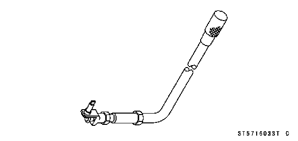
Special Tool - Pilot Screw Adjuster, E [A]: 57001-1603
#1 [A] and #2 [B] to the lower vacuum. • Open and close the throttle valves after each measure- ment and adjust the idle speed as necessary. • Inspect the vacuums as before.
gine vacuum synchronization.
○Check the bypass screw and its hole for carbon deposits.
screw and the hole, using a cotton pad penetrated with a high-flash point solvent. ○Replace the O-ring with a new one. ○Check the tapered portion [E] of the bypass screw for wear or damage.
• Turn in the bypass screw until it seats fully but not tightly.
• Repeat the same procedure for other bypass screws. • Repeat the synchronization.
the main throttle sensor (see Main Throttle Sensor Output Voltage Inspection in the Fuel System (DFI) chapter).
|
||||||||||||||
|
|
Последнее изменение этой страницы: 2016-08-10; просмотров: 683; Нарушение авторского права страницы; Мы поможем в написании вашей работы! infopedia.su Все материалы представленные на сайте исключительно с целью ознакомления читателями и не преследуют коммерческих целей или нарушение авторских прав. Обратная связь - 216.73.216.20 (0.009 с.) |


 Oil Filter Wrench: 57001-1249
 • Remove:
 • Remove:
 NOTE
NOTE
 • Clean the element [A] in a bath of high-flash point solvent,
 • Install the element unit [A] with the foam element side (gray) [B] facing down.
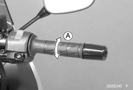 Throttle Control System Inspection
 • Check the throttle grip free play [A].
 If necessary, adjust the throttle cable as follows.
 • Remove the right center fairing (see Center Fairing Re- moval in the Frame chapter).
 Engine Vacuum Synchronization Inspection
 • Connect a highly accurate tachometer to one of the stick
 • Start the engine and warm it up thoroughly.
 If any one vacuum is not within the specification, turn in the bypass screws until it seats fully but not tightly.
 • Turn out the bypass screw of the higher vacuum between
 • Remove the bypass screw [A], spring [B], washer [C] and O-ring [D].